An Arduino digital LED controller
23 August 2018, posted in Miscellaneous
Since building my current Hackintosh in 2012 I have made a number of changes to the hardware. After all, upgradability is one of the key benefits of a PC over a computer made by Apple. At this point the computer is down to just one harddrive in addition the system SSD, it is back to air-cooling for the CPU, and all components are very quiet. So, a couple of months ago I decided to get a new case, better matching the hardware in use now.
The trend in the PC industry to use more and more LED lighting hadn’t escaped me, and I feel that, in reasonable amounts, this can actually add to the look. What I had in mind was a single coloured fan on the front of the computer, but somehow I couldn’t bring myself to buy one of the many, comparatively expensive, LED-lit fans on the market, because they are, in almost every aspect, worse than the fans I have. It was then that I discovered Phanteks’ Halos Digital RGB fan frames; basically very thin frames with LEDs that are inserted between the computer case and the fan.
Now my new problem, and opportunity, was that these fan frames contain 30 individually addressable RGB LEDs, i.e. each of the LEDs can have a different colour at any moment in time. My mainboard is obviously way too old to have RGB support so I decided to use an Arduino board instead.
Wiring
From a hardware perspective the setup was straight-forward. The frame connector has three pins only: ground and 5V for power, and data input to control the LEDs. By the way, each of the 30 LEDs has a tiny embedded controller to interpret the protocol sent over the data wire. After finding a library that implements this protocol it was trivial to get to my first prototype.

The frame is powered from the Arduino (red and black cables), and data input is connected to a digital pin (green cable). That’s all. These new LED solutions don’t require any additional circuitry for voltage control or shifting, and the power requirements of a single Digital Halos frame are met by the Arduino.
The cable on the left of the picture is the fan cable, which in this setup is connected to a steady 12V source to make the fan spin. The visual effect would be greatly reduced if the fan was standing still. In fact, the fan used here has black blades while the actual fans in my computer case have white blades, which further improves the effect.
Programming
The library mentioned above is provided by Adafruit, who, among other things, make a number of digital RGB LED products under the NeoPixel brand that use the same underlying technology as the Halos frames.
Usage of the library boils down to two key functions, one to set the colour value of a given LED and one to send data to the LEDs. The following code, for example, sets all LEDs to a bright blue:
for (int i = 0; i < frame.numPixels(); i++) {
  frame.setPixelColor(i, frame.Color(0, 0, 255));
}
frame.show();
For the rainbow pattern shown in the prototype picture above a few calculations are needed to get the RGB values for each LED, but that “just” a bit of math.
More wiring, and more programming
With the basics in place I spent a while playing with different patterns. I liked a good few of them and so the idea evolved to load the Arduino with a number of patterns that could be switched somehow. My eye fell on the reset button on my case, which I never use. A connection from the button to the Arduino, a bif of interrupt code, and a pattern switcher was implemented.
Thinking further about communication between the PC and the Arduino, and not forgetting that there is a Hackintosh in the case, I thought it would be interesting to see whether I could implement a “breathing” status indicator when the computer is asleep, just like the Macs used to have them. It turns out that the USB ports are powered when the computer is asleep, keeping the Arduino running and the LED frame lit. With another cable from a status LED pin on the mainboard to the Arduino the program on the Arduino could switch to a different pattern when the computer is asleep. The code for the breathe pattern (in blue) is also reasonably simple:
void breathe()
{
  static uint8_t counter = 0;
  counter = (counter+1) % 256; // modulo operation just to express intent

  uint8_t x = frame.sine8(counter);
  uint8_t l = frame.gamma8(x/2+8);

  for (int i = 0; i < frame.numPixels(); i++) {
    frame.setPixelColor(i, frame.Color(0, 0, l));
  }
  frame.show();

  delay(14);
}
At first, the transition between light and dark during the breathing didn’t look right. The simple reason is that the LEDs have a gamma curve, just like the LED panels in monitors. Lukily, the library comes with a gamma curve, encoded in a handy lookup table, which is being used in the code above.
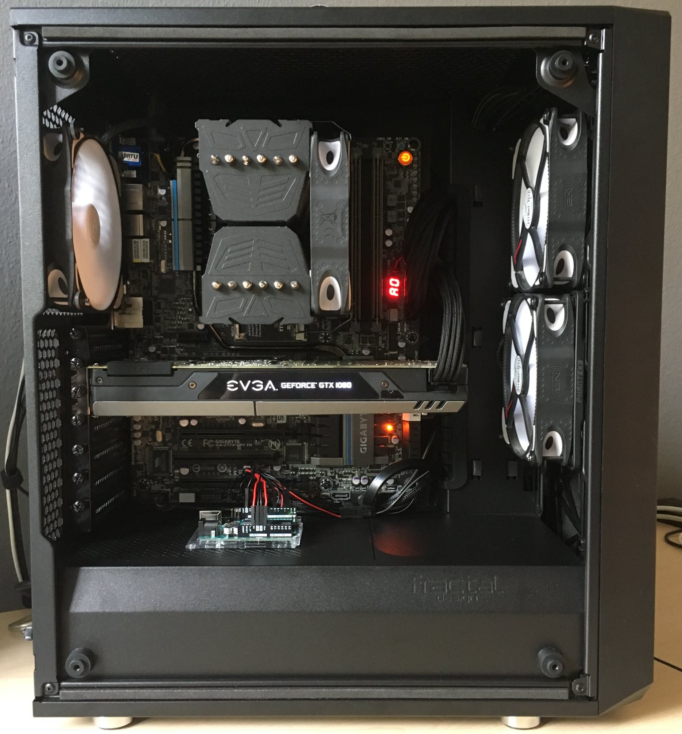
Assembly
All of the headers required for this project are at the bottom of the mainboard, which made the PSU shroud at the bottom of the case a perfect location for the Arduino.
The Halos frame is also visible in the picture. It is located between the case and the lower intake fan on the right side. If you look closely you can see the word Phanteks on it.
Outlook
To be completely honest, I did think about adding a Wave Shield to the Arduino and hook up a speaker to play the Mac startup chime when the computer is turned on, but that is for another project.